Turbofan:Blades
Blade design and manufacturing
This page explains how blades should be designed for efficiency, and how can a simple and low-cost manufacturing be relevant.
Blade fixation
The root/fixation/insert of the blade is discussed on the related subsystem design page: compressor, turbine or fan. In summary, real engines use a fir tree shape to hold the blade centrifugally, while keeping them free axially. They are generally fixed using a locking screw. This design allows for easy replacement of damaged blades, but is quite complex to manufacture, and requires lots of parts. Since our engine will be smaller, using fixing screws may not be feasible, and blades are subject to less centrifugal stress. Simpler blade fixation mechanism should be relevant.
Blade designs for efficient air flow
Blades have to be carefully designed, because the overall efficiency of the engine largely depends on their design.
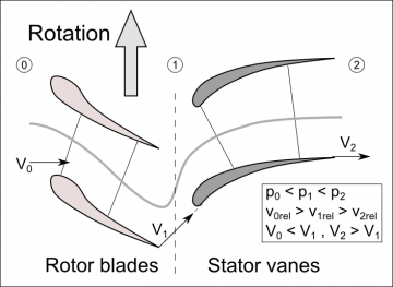
Stages. They are not only made of blades on the rotor, but also blades on the stator, generally called vanes. A stage is then a pair of a rotor stage and a stator stage, in this order. The stator prevents a rotating air flow to form inside the engine (swirl), driven by the action of the rotor blades. Stator vanes redirect the airflow in the more appropriate direction for the next rotor stage. They increase the energy of the gas (enthalpy) by removing the swirling effect that impairs it.
Blade shape. Most basic design of a fan has flat-shaped blades. Twisted blades with a flat section are an improvement, taking into account the difference in apparent airflow velocity and torque all along the blade. Next step is to have a non-flat section, but an airfoil section. This has been proved to be the only design meeting efficiency requirements of the turbine engines, in 1926 by Alan A. Griffith. Finally, modern engines are designed with curved edges for the fan, for optimal known efficiency as well as for noise reduction.
Rotor/stator gaps. Highest efficiency is reached in turbofans when gaps are reduced between blades and the stator, or between the rotor and stator blades. As always, good efficiency means good high precision and higher cost. Anyway, the precision of blades will have to be very good if we don't want it to dislocate when it reaches the high rotations-per-minute achieved by the engines.
Design of stages is linked to the energy the blades have to give (compressor and fan) or take (turbine) to the air flow. To better define and understand that energy, we will use standard thermodynamic parameters of gas, a.k.a state variables of a gas, on which are based quantities like the enthalpy: temperature, volume, pressure. We will also use the velocity because the actual work given by a turbofan engine is related to the mass flow rate of the gas expelled by the engine, which relates to velocity of this gas and the state variables.
Gas variables: temperature, pressure, velocity
Fan design
The main goal of the fan is to increase the mass flow rate, mainly by increasing the velocity. The mass flow is related to the area of the fan blades and the angular speed of the fan. To increase the velocity, the simplest way is to reduce volume, in other words create a nozzle. The fan duct will thus have to act as a compressor on the aft-end. On the front-end, it is generally designed as an expander, to increase the pressure, allowing more efficient work on the air flow.
Compressor design
The main goal of the compressor is to increase pressure. A compressor stage is composed of a blade-mounted rotor and a vane-mounted stator. The shape of the blade is an airfoil and as the gas flows through the rotor and the stator it gains static pressure, since the blades form a expander. Speed is however gained in the rotor section, because of the high rotational speed of the blades. Stator vanes remove the resulting swirl, and converts the velocity (dynamic pressure) to static pressure, thus increasing again the pressure. The volume occupied by the gas can consequently drop as the pressure increases, intake area will be greater than compressor discharge area. Due to friction and pressure rise, temperature is increased too.

Turbine design
The main goal of the turbine is to extract energy from the hot and fast gas discharged by the combustion into mechanical (rotational) work. Pressure and temperature may remain constant through the turbine, and high velocity and pressure will provide better efficiency [to be verified].
Mechanical constraints
Blades on all three parts of a turbofan engine undergo heavy mechanical constraints due to high rpm achieved by the rotor, the high temperature in the turbine section and non-negligible temperature in the end of the compressor section, and the high pressure of the gas on which work is performed.
Fan blades are not made of plain metal in real engines. In the eighties, they were made in honeycomb composite sandwich material, they are now made in triangular sandwich structure. For an engine of the size we are targeting, fan blades may be built with plain carbon fiber, like the Schuebeler HST high quality R/C engine.
Compressor blades are made of titanium alloys, providing high strength and rigidity at these temperatures.
Turbine blades are made of nickel alloys, better sustaining the high temperature, and still at higher strength than steel.
Manufacturing propositions
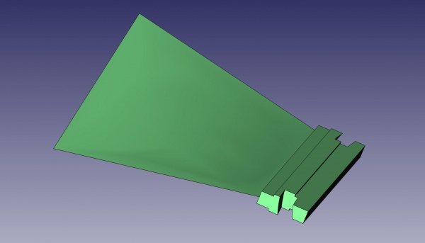
Hot pressing, as a Hot working process, is used to manufacture real-engines' blades, and hot isostatic pressing possibly too, as explained on the How are made turbine blades video. I believe that a hot forging press can be done cheaply considering the small size of our blades. For the main fan, it thus may not be used.

The above picture lacks the airfoil section of the blade, because the CAD software we use doesn't currently support it.
Work-hardening and heat-resistance processing have to be studied, and depend on the crafting method used in the first place.
The high-pressure turbine blades have to face very high temperature and pressure. On real engines, they are made of titanium and nickel-based superalloys. Since the required lifetime is lower in our case, we may achieve a working engine with cheaper metals, like steel or nickel-rich alloys for the turbine blades. Historically, the temperature that turbine blades could sustain greatly improved over time, as well as engine efficiency. We can take these two factors and design a reasonably short-lived (6hrs, 3 missions?) and medium efficiency engine.
Material for compressor blade and fan blade can probably be aluminum or aluminum alloys like 2024 (dural) or even 7075.
The blade insert will have to be milled at some point, unless if it is casted or pressed.
Sonic speed at the tip of a 160mm fan is achieved at around 40000 rpm, for 120mm a fan, required rpm are 50000. Strength of the blade insert and stage's hub should be calculated from this speed and expected blade weights, to verify the capability of materials before fixing engine characteristics.