Turbofan:Alternative Designs
Alternative design for turbofans
All recent jet engines have the same basic architecture: a fan at the front, the turbine engine acting as the power plant behind it. Their flows mix at the exhaust, inside the engine for low bypass ratio engines and outside, in atmosphere, for high bypass ratio engines. Early designs of turbofans were actually created by adding a ducted fan on the aft part of existing turbojet engines. They were not so bad in terms of efficiency compared to front-mounting engines, but the main issue was that the fan was evolving in a hot gas flow, which would eventually corrode or induce fatigue on it more than when it blows fresh air as in a front-mounted fan design.
A second fact is that high-efficiency engines, or modern engines, all use axial-type compressor and axial-type turbine. Some early or less power-requiring designs feature a centrifugal-type compressor, and only one engine to our knowledge had a centrifugal turbine, the HeS 1 (picture), the first that actually flew a plane.
From these two facts, we propose a novel design for turbofans: an axial-compressor, hybrid-turbine, aft-mounted ducted fan.
- The hybrid turbine uses both axial and centrifugal designs, in which the hot gas flow would be slightly diverted from its linear course, while extracting some of its energy for shaft rotation work. The centrifugal part is crossed by the flow from the centre to the outer, contrary to what has been done in the HeS 1.
- The air breathed by the fan would be the mixed flow of the traditional fresh intake and the turbine discharge, providing higher temperature to the fan flow. The main advantage of this hot air is the increase in speed of sound and the ability to drive the fan at transonic regime on the same spool than the compressor operating at transonic regime too. Multi-spool engines have been created to allow such features in classical engines.
The engine will inevitably be longer because room has to be made for the flow-mixing section. This will make the engine slightly heavier too.
Hybrid turbine
work in progress
The reasons why gas turbines employ axial-turbine stages should be listed here. For turbojets this is obviously due to the fact that the hot gas stream at engine discharge is what gives thrust, so the path of the hot gas from the turbine to the nozzle should be kept as linear as possible. For turbofans, the core engine exhaust also plays a role in providing thrust, generally around 10% of the total engine's thrust.
Diverting the hot gas flow results in heavy loss of kinetic energy. Passing through a centrifugal-turbine extracts lots of energy from the gas and does not allow further work to be done from it. It also means that a centrifugal-turbine has to cope with much higher temperatures than axial-turbines, which can be a real show-stopper since axial-turbines already have important issues with temperature.
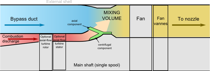
In our case, we need to divert the hot gas flow in order to have it mixed properly with the cold air from the bypass. The diversion thus should be less than 45° and the turbine will be operating in a hybrid-mode, with a centrifugal-mode upstream and axial-mode downstream, harvesting energy from the diverted flow. This will result in a turbine having boomerang-shaped blades, as the green part depicted below.
Bypass flow and core discharge flow mixing
work in progress
The hybrid turbine will be the last part crossed by the flow before the mixing. The hot flow will be abruptly expanded in the mixing area, converting the dynamic pressure (velocity) to static pressure. What about the temperature? if it's an isentropic irreversible expansion the temperature slightly decreases, if it's an adiabatic irreversible expansion the temperature decreases, but here no work is done so it's more like an non-ideal adiabatic free expansion for which the temperature may slightly change (to be verified, it does not change for an ideal gas); however, in a steady flow, an adiabatic diffuser (if we treat the heat exchange later in the mixing) increases both pressure and temperature.
The static pressure increase and the velocity reduction will allow the fan to operate in an even more efficient way.
An exhaust diffuser may have to be designed to control the expansion and the mixing in order to adjust the flow direction and velocity for the fan intake.
The mixing can be seen as a preheat, like the usual reheat to lesser extent, but before the fan has done its compression work, still allowing the nozzle to accelerate further the exhaust gas and thus providing a higher mass flow rate (= higher thrust and specific power).
Fan operation
work in progress
Main question: is the fan much less efficient when it blows hot air than cold air? Is this efficiency overtaken by the efficiency increase in transonic regime versus subsonic? The air density is 1.9 times lower at 150°C (423K) compared to -50°C (223K), which would mean that the fan is nearly two times less efficient, if the pressure stays constant during the heating, but does it? Probably not, since the hot gas is expanded at core's discharge, it trades its dynamic pressure to higher static pressure.
Thrust depends on the mass flow rate of expelled material. Higher temperature means that the density is lower, and thus that the mass flow rate should be lower too.
Properly mixing the two flows would allow the fan to be build with metals supporting low temperatures, like 2000- or 7000-series aluminium alloys.
Thermodynamic analysis
Turbine engines are assimilated to a Brayton cycle. It consists of 4 processes:
- adiabatic compression - made by the compressor
- isobaric heat addition - made by the combustion
- adiabatic expansion in two steps - first made by the turbine, the extracted work is used to drive both the compressor and the payload. In the case of a turbofan the payload is the fan. Then, the nozzle finishes the expansion and exhausts gas at atmosphere pressure.
- isobaric heat rejection - made when the exhaust gas returns in the atmosphere.
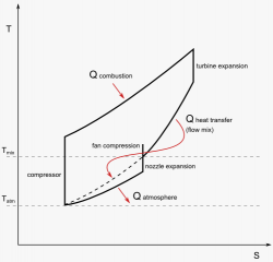
In our approach, the expansion has to be considered as two different steps because there is a heat exchange between the two. Also, the fan doesn't operate in an adiabatic process since there is a heat input made by the core engine exhaust gas mixing. The two cycles, the core engine cycle and the fan cycle are now combined. The new process are:
- adiabatic compression - made by the compressor
- isobaric heat addition - made by the combustion
- adiabatic expansion - made by the turbine
- isobaric heat rejection - made by the flow mixing
- adiabatic compression - made by the fan
- adiabatic expansion - made by the nozzle
- isobaric heat rejection - made when the exhaust gas returns in the atmosphere.

Example implementation: full transonic engine design in a single spool with 2.1 BPR
We speak here of virtual bypass ratio (BPR) because as flows are mixed before the fan intake, there is no clear separation between flows of the fan and of the engine's core. However, there is still an inlet area for the compressor and one for the fan, and the ratio between the two mass flow rates going into each is what we call the virtual bypass ratio (VBPR). The real bypass ratio (BPR) is thus the ratio between the sum of the fan duct mass flow rate and the core's mass flow rate over the core's mass flow rate (MFR_fan + MFR_core) / MFR_core.
Let's take an example turbofan engine with a 13cm fan and a 9cm core diameter. The VBPR for this engine is around 1.08 if we consider the inlet flow speeds to be identical on both intakes ((13²-9²)/9²), and the BPR is in fact 2.09 (13²/9²).
The main advantage of our aft-fan engine design is that both the first stage of the compressor and the fan can operate at transonic speeds. A blade or a fan is said having a transonic operation when the flow passing through the fan it is subsonic, but its rotation speed makes the blades' tips move at supersonic velocities, their root staying generally subsonic. It thus depends on three main factors: the diameter of the fan on which the blade is mounted, the rotation speed of the fan, and the speed of sound M, which depends on the temperature of the air flow. Transonic operation enables higher compression ratios than subsonic operation, with a lower efficiency as a drawback, around 5% less because of the drag induced by shock waves. It is likely that more noise is generated too, but it's not a concern for us, contrary to usual aircraft engines.
The key to our dual-transonic operation mode is the temperature, which changes M. In high altitudes, or in particularly cold days, the temperature difference between the cold air entering the compressor and the hot mixed gas at the fan intake is large enough to enable the dual-transonic operation. The fresh air can go down as low as -57°C in altitude, which gives a sonic speed of 295m/s. On the other hand, the air that the fan blows will be preheated by the turbine exhaust gas. If we fix a 200°C rise of this air flow, the sonic speed can be around 430m/s.
If we take back our example above with the 13cm fan and 9cm compressor with the 200°C heating of the fan inlet flow, we achieve sonic speed with the same rotational speed, more than 60000rpm, for both the compressor first stage and the fan, which is unique for a 2.1 or even a 1.1 BPR turbofan engine.
The reason why we try to have a transonic operation on the compressor, even more than on the fan, is that since we aim a low number of stages for the compressor for cost reasons, it's not able to have a high overall compression ratio (CR). With a transonic-operating first stage, we hope to have at least 2.0 CR for it, instead of the maximum 1.6 CR in subsonic operation, which would greatly improve the overall CR of the compressor. Depending on the temperature rise induced by this first stage, the second stage may be able to operate at transonic or near sonic speeds too, although unlikely. Higher efficiency of the fan will allow higher mass flow rate and thus higher thrust of the engine, which is obviously great too.
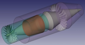
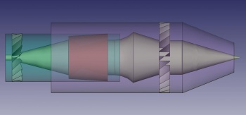
The above schematics may not reflect actual proportions and have transparency inconsistencies. That said, the engine's core is the green internal tube. The fan sketched inside it, at the front of the engine, is the compressor's first stage rotor. The stator and other stage are not represented, and will obviously be placed on the conic part behind it. The red part is the annular combustor, not easy to see clearly in these pictures. The turbine is not represented either, but an axial rotor should be placed right after the combustor, and the hybrid turbine will be milled in the shaft in the curved part after a second axial turbine guide vane. We can see that the discharge of the turbine is mixed with the inlet air of the aft-mounted fan. The fan duct is thus longer than in traditional front-mounted engines, but the nozzle can be closer to the fan, allowing to work on both core and fan flow.


