Uploads by Vincent
From NPrize
Jump to navigationJump to search
This special page shows all uploaded files.
| Date | Name | Thumbnail | Size | Description | Versions |
|---|---|---|---|---|---|
| 00:45, 6 November 2017 | Solar system exploration with cubesats.pdf (file) | 1.06 MB | This presentation was made at SpaceUp Cote d'Azur (Nice, France) in October 2017. The goal was to explain the challenges of solar system exploration using small satellites, emphasizing that it will cost a lot of money on either launches or reliable spa... | 1 | |
| 00:14, 12 March 2013 | Pegasus wings.gif (file) |  |
12 KB | 3 views of Orbital Pegasus' wings | 1 |
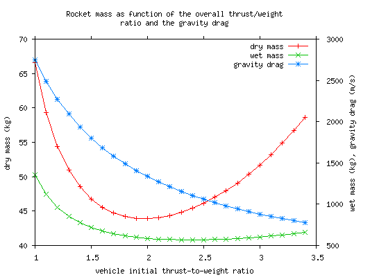
| 03:33, 12 December 2012 | Gravity drag and thrust to weight.png (file) |  |
6 KB | Updated with the gravity drag curve and make the image larger. | 2 |
| 01:42, 12 December 2012 | Rocket mass.c (file) | 21 KB | clarification about the propellant mass. vehicle_wet_mass is the dry mass + the burnt propellant mass, but it doesn't include the propellant taken aboard and evaporated during the ascent. The output indicates the ground value now. This is still version 3. | 4 | |
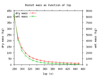
| 20:59, 11 December 2012 | Isp.png (file) |  |
3 KB | starting at 280 instead of 270 | 2 |
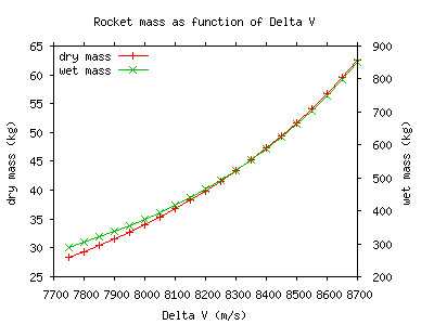
| 20:53, 11 December 2012 | DeltaV.png (file) |  |
4 KB | Graph representing rocket dry and wet mass as function of the Delta V. Done with version 3 of File:Rocket_mass.c, overall thrust-to-weight ratio is 2.5 and Isp is 340s. | 1 |
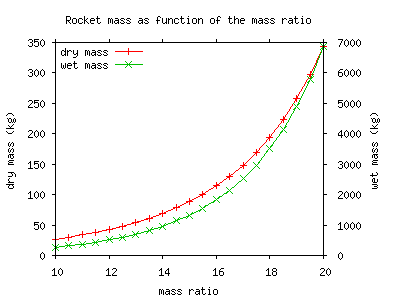
| 20:09, 11 December 2012 | Mass ratio.png (file) |  |
4 KB | Updated with version 3 of File:Rocket_mass.c. Delta V is 8300 instead of 9000 m/s too, and overall thrust-to-weight ratio is 2.5 instead of 1.25. | 2 |
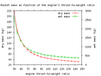
| 20:08, 11 December 2012 | Engine thrust to weight.png (file) |  |
4 KB | Updated with version 3 of File:Rocket_mass.c. Delta V is 8300 instead of 9000 m/s too, and overall thrust-to-weight ratio is 2.5 instead of 1.25. | 2 |
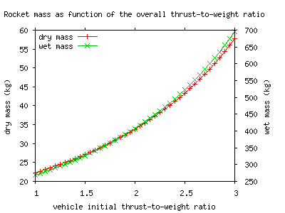
| 20:06, 11 December 2012 | Overall thrust to weight.png (file) |  |
4 KB | Updated with version 3 of File:Rocket_mass.c. Delta V is 8300 instead of 9000 m/s too. | 2 |
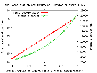
| 20:04, 11 December 2012 | Final acceleration.png (file) |  |
4 KB | Updated with version 3 of File:Rocket_mass.c. Delta V is 8300 instead of 9000 m/s too. | 2 |
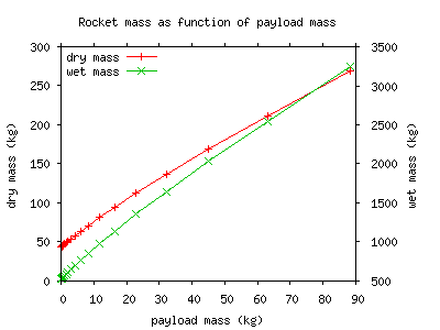
| 20:02, 11 December 2012 | Payload 0-80kg.png (file) |  |
4 KB | fixing update | 3 |
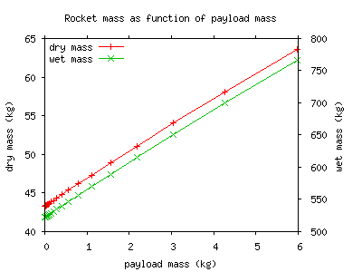
| 19:57, 11 December 2012 | Payload 0-6k.png (file) |  |
3 KB | Updated with version 3 of File:Rocket_mass.c. Delta V is 8300 instead of 9000 m/s too. | 2 |
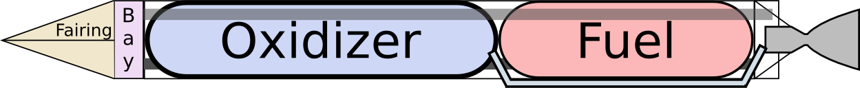
| 00:26, 11 December 2012 | Rocket model.png (file) | 36 KB | Rocket model illustration for the computed rocket model: File:Rocket_mass.c | 1 | |
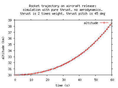
| 03:10, 27 November 2012 | Rocket ignition.png (file) |  |
3 KB | Graph of the rocket trajectory for first moments after release, assuming ignition at the time of the release, a thrust vector with 45 deg pitch, and an overall thrust-to-weight ratio of 2. No atmosphere considered whatsoever. | 1 |
| 02:01, 24 November 2012 | Heat transfer to rocket tank.c (file) | 13 KB | Program calculating the heat transferred to a cryogenic tank (typically LOX) for balloon- or air-to-orbit vehicles. Two heat transfer approximations are done. * when the vehicle is waiting on the ground after tank filling and before it lifts-off from the | 1 | |
| 02:59, 17 November 2012 | ISA atmospheric model.c (file) | 3 KB | C Implementation of the international standard atmosphere ([https://en.wikipedia.org/wiki/International_Standard_Atmosphere ISA]) model. This is a port of http://www.digitaldutch.com/atmoscalc/ . | 1 | |
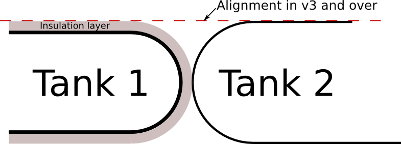
| 01:37, 9 November 2012 | Rocket mass tanks v3.png (file) |  |
31 KB | tank model for rocket mass version >= 3 | 1 |
| 01:36, 9 November 2012 | Rocket mass tanks v1-2.png (file) |  |
29 KB | white bg | 2 |
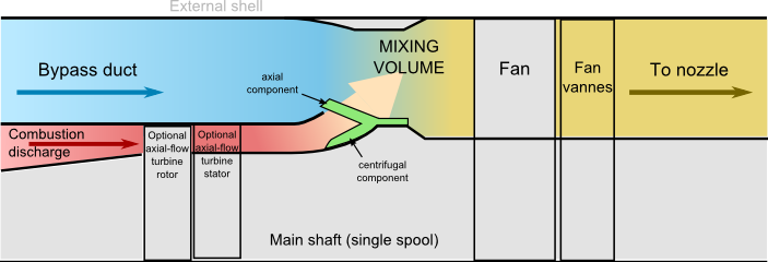
| 23:38, 31 May 2012 | Hybrid turbine.png (file) |  |
38 KB | glimpses of an expander and minor improvements | 4 |
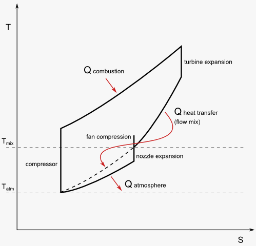
| 22:28, 28 May 2012 | Thermodynamic diagrams.png (file) |  |
32 KB | T-S diagram for the mixed/hybrid turbofan. | 1 |
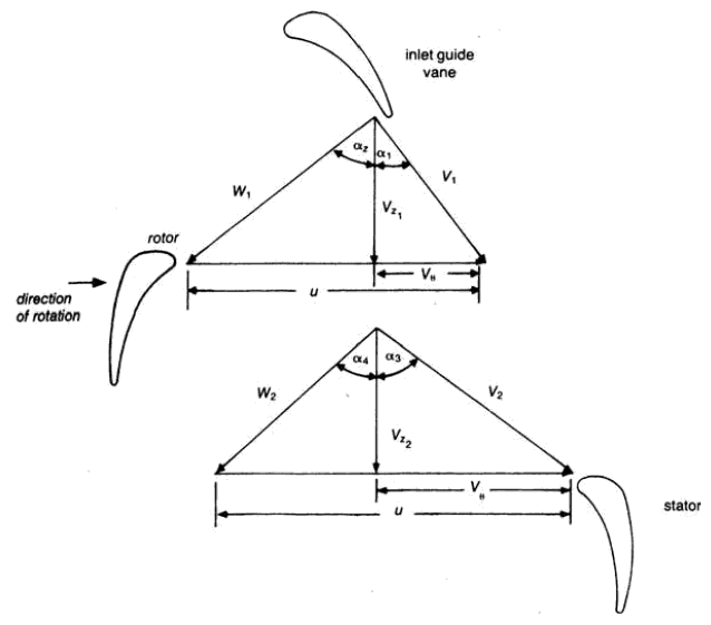
| 01:39, 27 November 2011 | Velocity triangles.png (file) |  |
27 KB | Velocity triangles for axial compressor blades. Source is the chapter "2.0 Axial-Flow Compressors" from M. P. Broyce. | 1 |
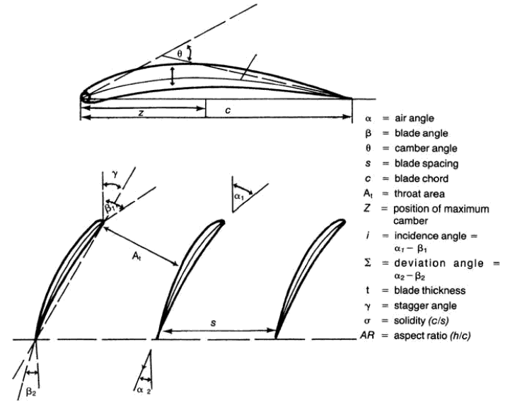
| 01:29, 27 November 2011 | Blade nomenclature.png (file) |  |
46 KB | Nomenclature of aerofoils (used in fan/compressor/turbine blades). Source is the chapter "2.0 Axial-Flow Compressors" from M. P. Broyce. | 1 |
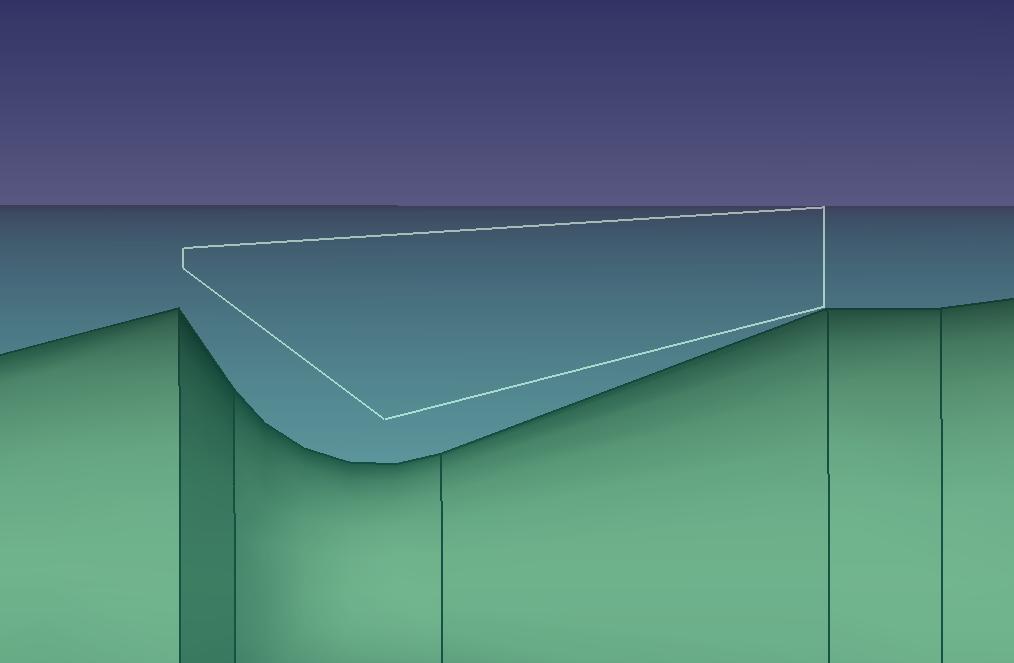
| 20:08, 2 November 2011 | Combustor sketch section.jpg (file) |  |
28 KB | Sketch of the combustor cross-section. The green part is the shaft, the transparent light blue part is the core shell. | 1 |
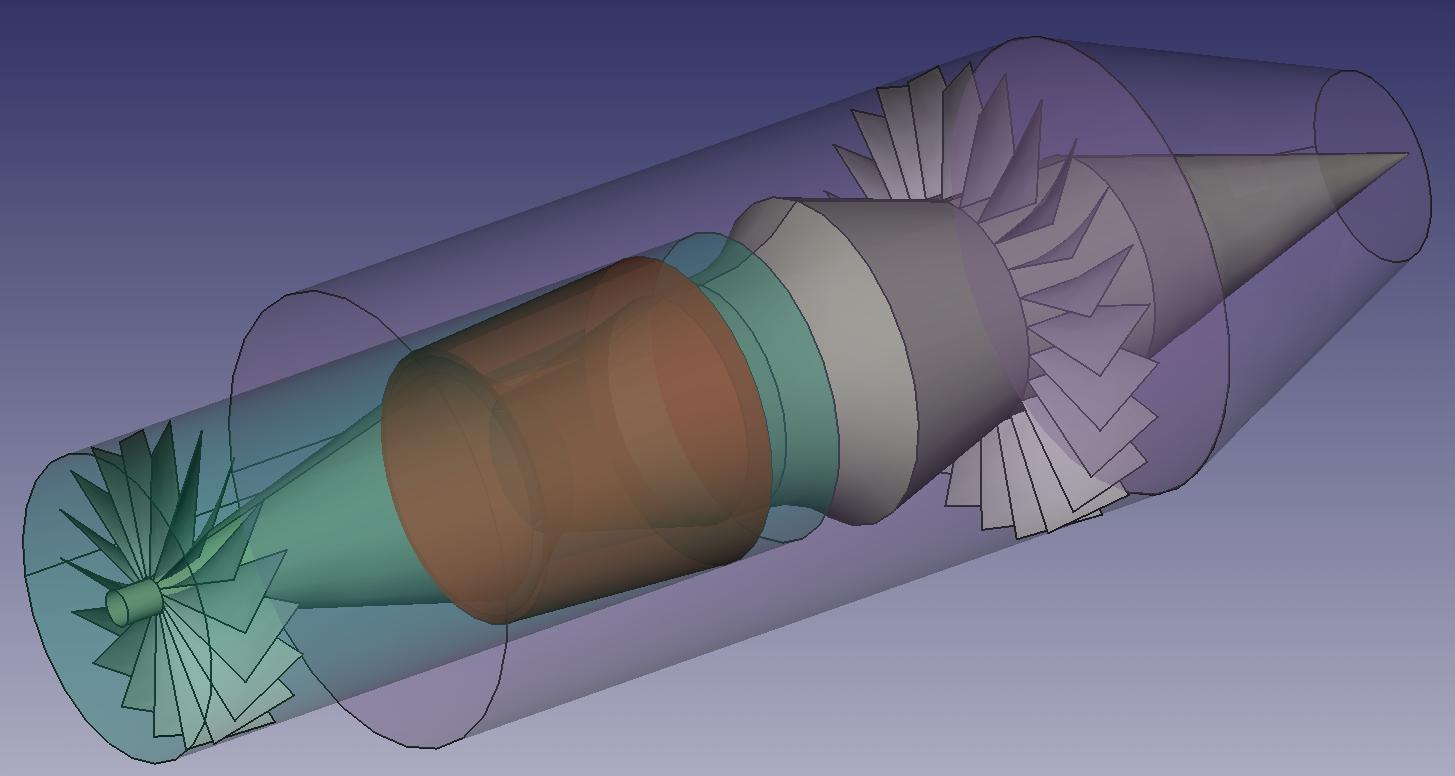
| 19:36, 2 November 2011 | Engine core and fan.jpg (file) |  |
66 KB | Sketch of the engine, with the core and the fan duct, aft-mounted fan and first stage compressor rotor drafted. The chamber is in red/brown. | 1 |
| 19:35, 2 November 2011 | Engine core and fan side.jpg (file) |  |
56 KB | Sketch of the engine, with the core and the fan duct, aft-mounted fan and first stage compressor rotor drafted. The chamber is in red/brown. | 1 |
| 23:27, 9 May 2011 | Compressor blades.svg (file) | Error creating thumbnail: /bin/bash: line 1: convert: command not found
|
22 KB | white bg | 2 |
| 23:26, 9 May 2011 | Compressor blades.png (file) |  |
73 KB | white background | 2 |
| 20:58, 28 February 2011 | Blade fixation simple.jpg (file) |  |
159 KB | fixing display artefact | 2 |
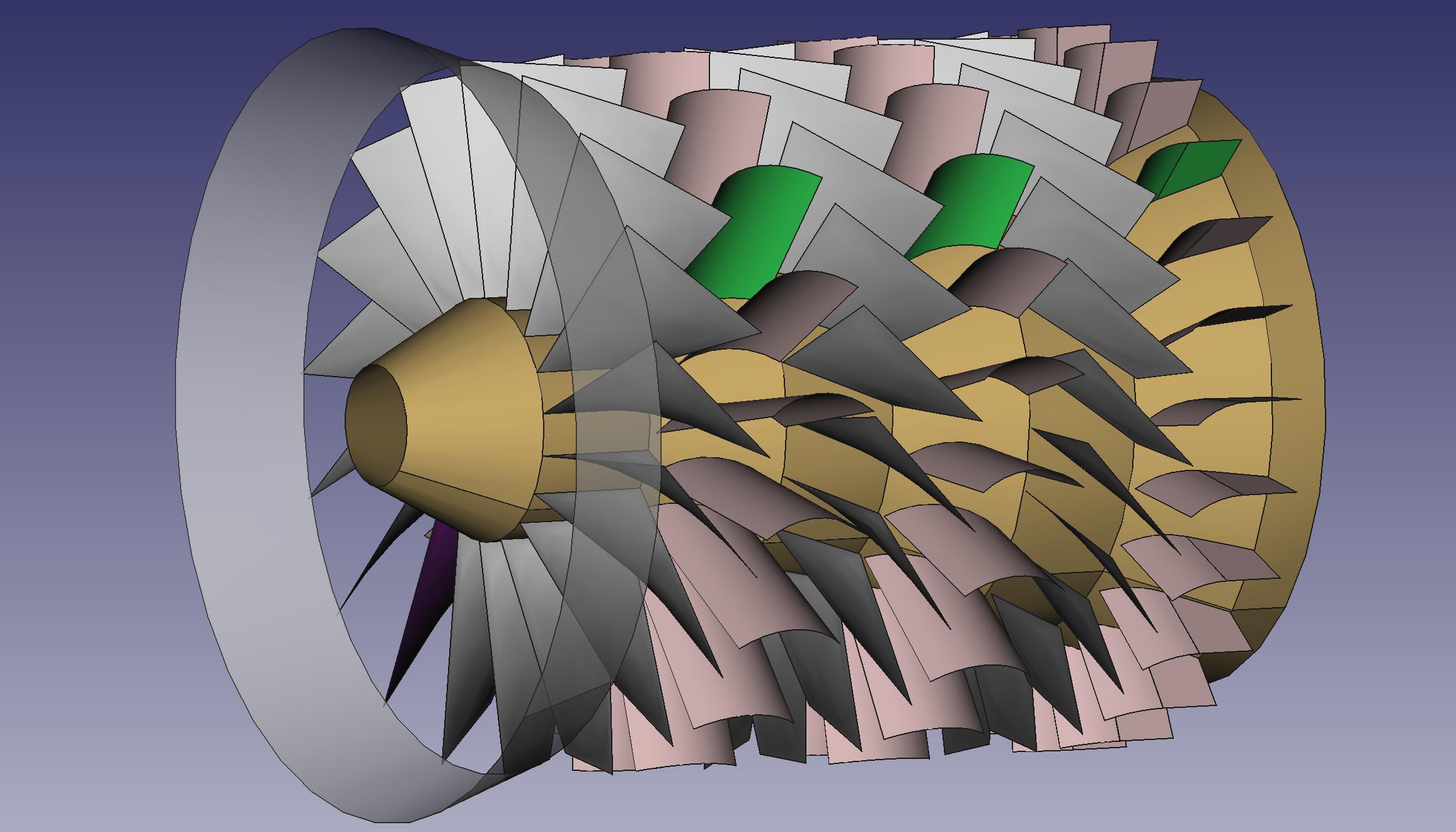
| 20:23, 28 February 2011 | Compressor side.jpg (file) |  |
173 KB | yellow shaft | 2 |
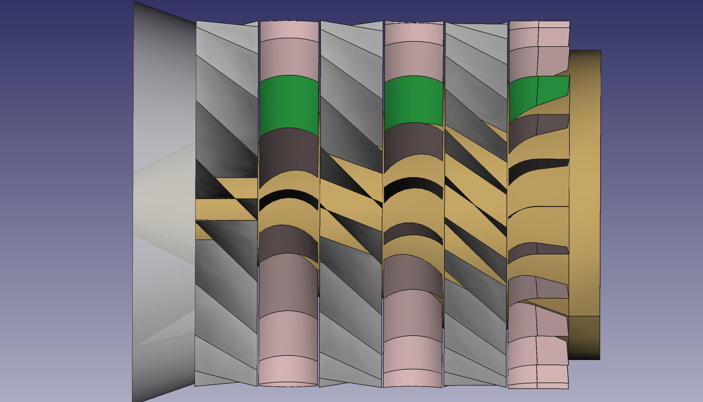
| 20:20, 28 February 2011 | Compressor noshell.jpg (file) |  |
221 KB | 2 | |
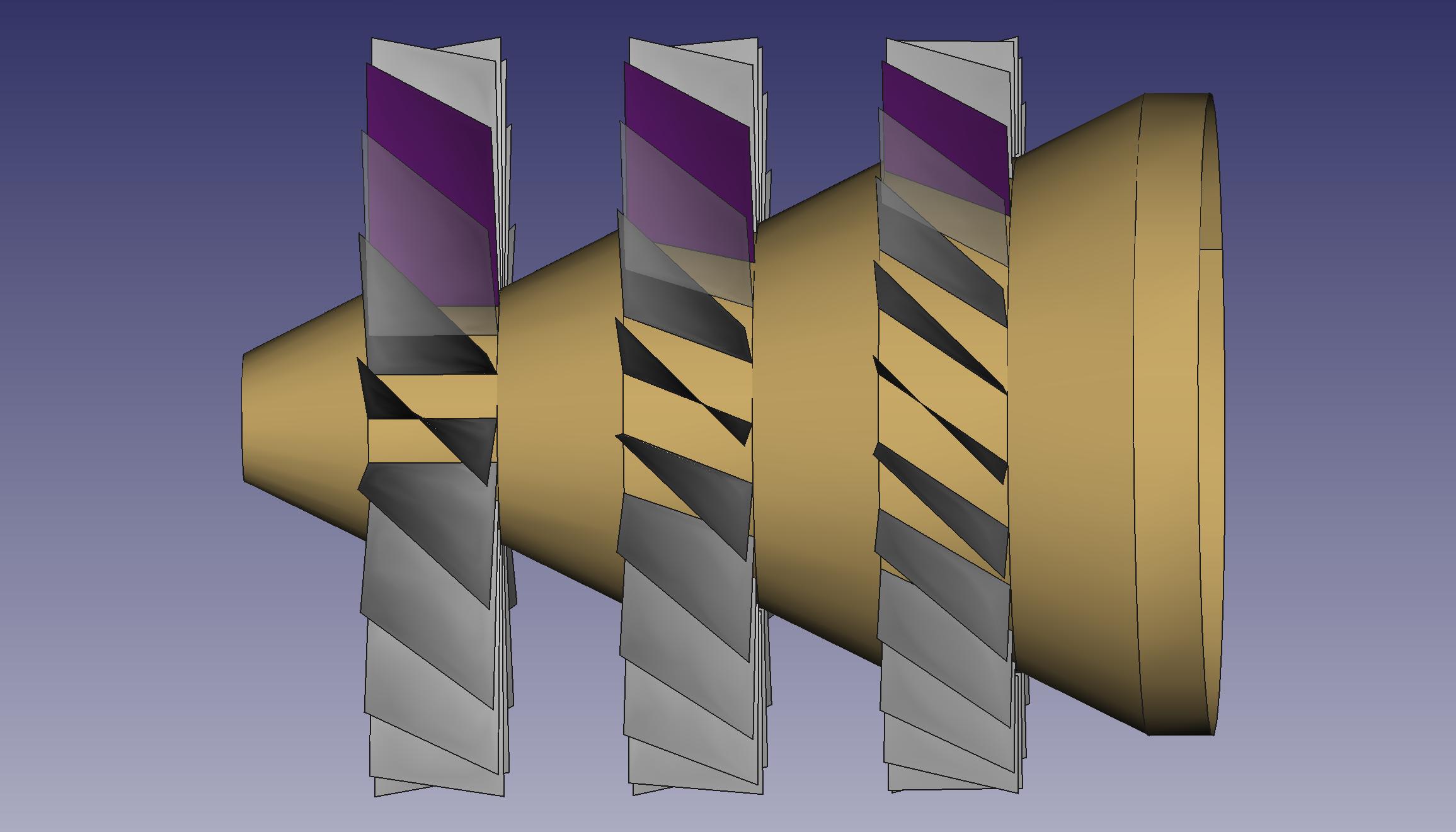
| 20:09, 28 February 2011 | Rotor side.jpg (file) |  |
150 KB | Rotor with its three-stages blades seen from the side. | 1 |
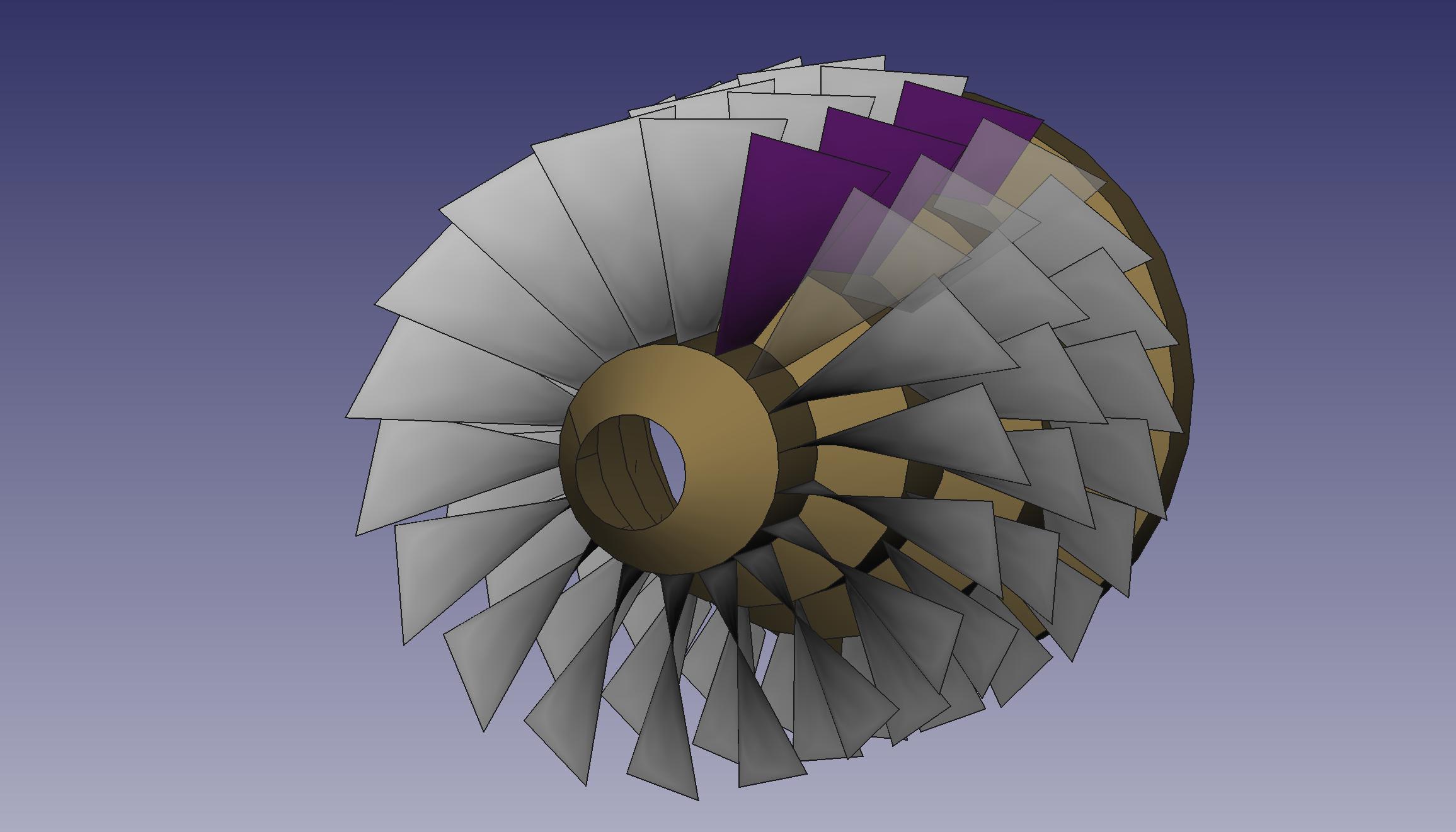
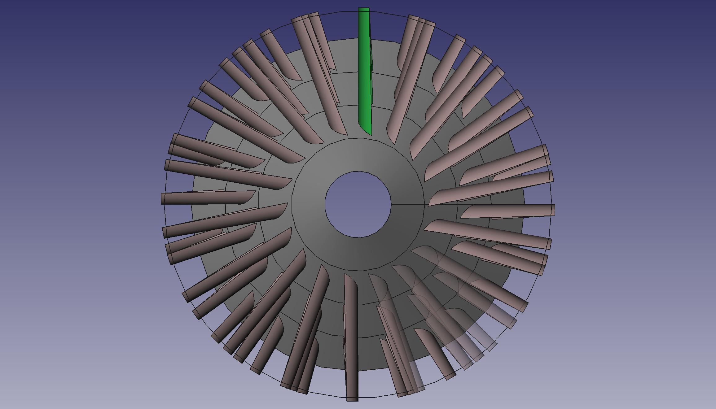
| 20:08, 28 February 2011 | Rotor front side.jpg (file) |  |
148 KB | Rotor with its three-stages blades, seen from nearly front. | 1 |
| 19:57, 28 February 2011 | Stator side.jpg (file) |  |
166 KB | Stator blades mounted on their shell and the shaft profile visible, nearly seen from the side. | 1 |
| 19:56, 28 February 2011 | Stator front.jpg (file) |  |
193 KB | Stator blades mounted on their shell and the shaft seen from the front. | 1 |
| 23:06, 23 February 2011 | Blade fixation2.jpg (file) |  |
180 KB | Close-up view on the blade fixation system (rear view). | 1 |
| 23:05, 23 February 2011 | Blade fixation1.jpg (file) |  |
172 KB | Close-up view on the blade fixation system. | 1 |
| 22:50, 23 February 2011 | Blade.jpg (file) |  |
86 KB | Turbine or compressor blade, with its milled insert. | 1 |
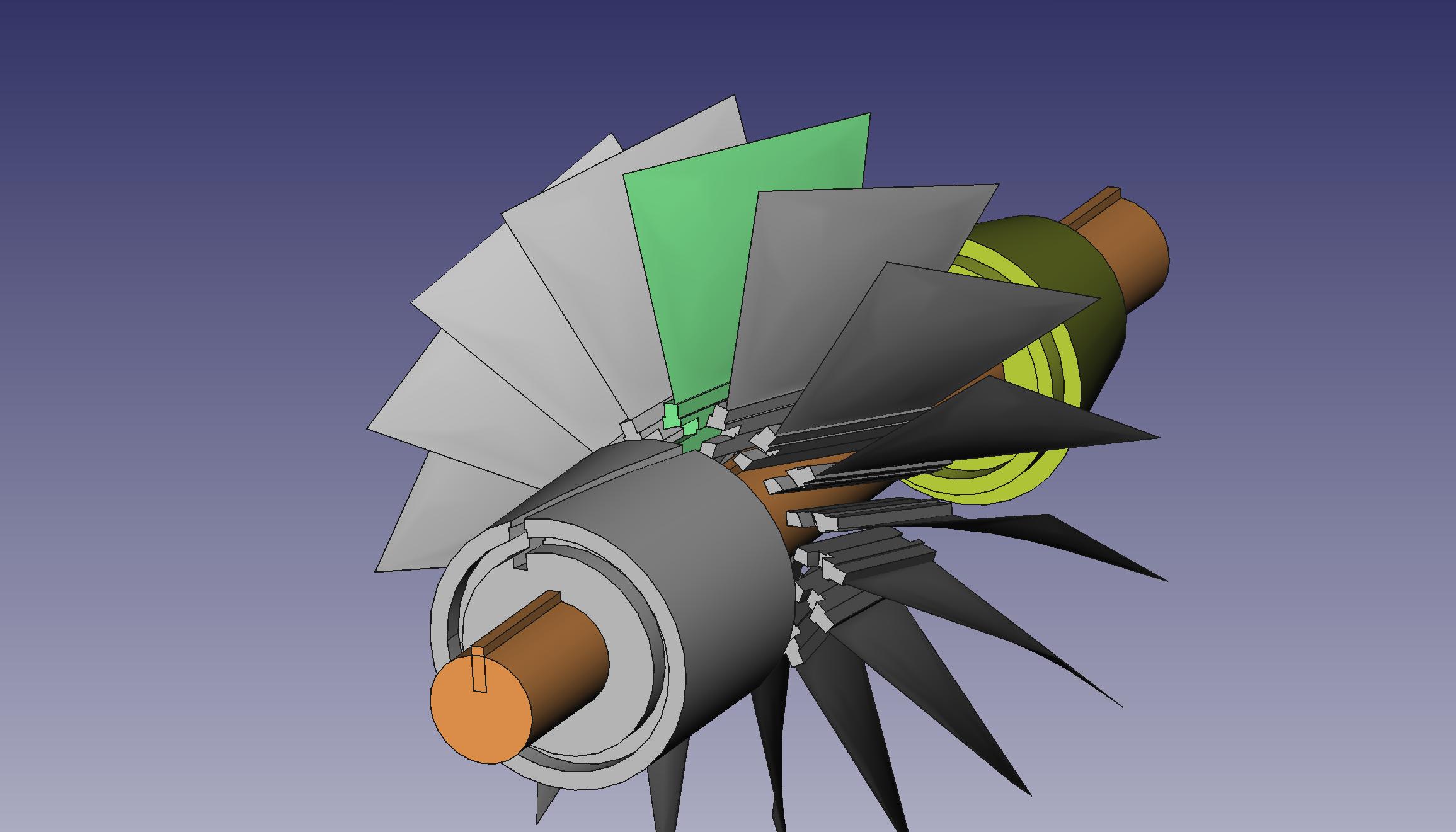
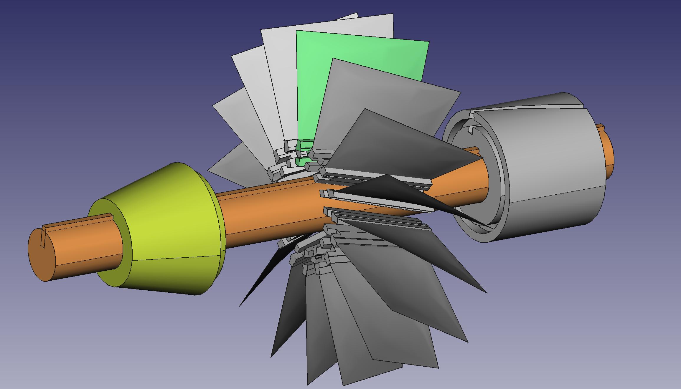
| 02:03, 22 February 2011 | Interblade2.jpg (file) |  |
149 KB | Exploded view of a simple compressor blade fixation design. The main shaft (orange) has one spline at least, allowing the blade support and the conic parts to be coupled to the shaft. | 1 |
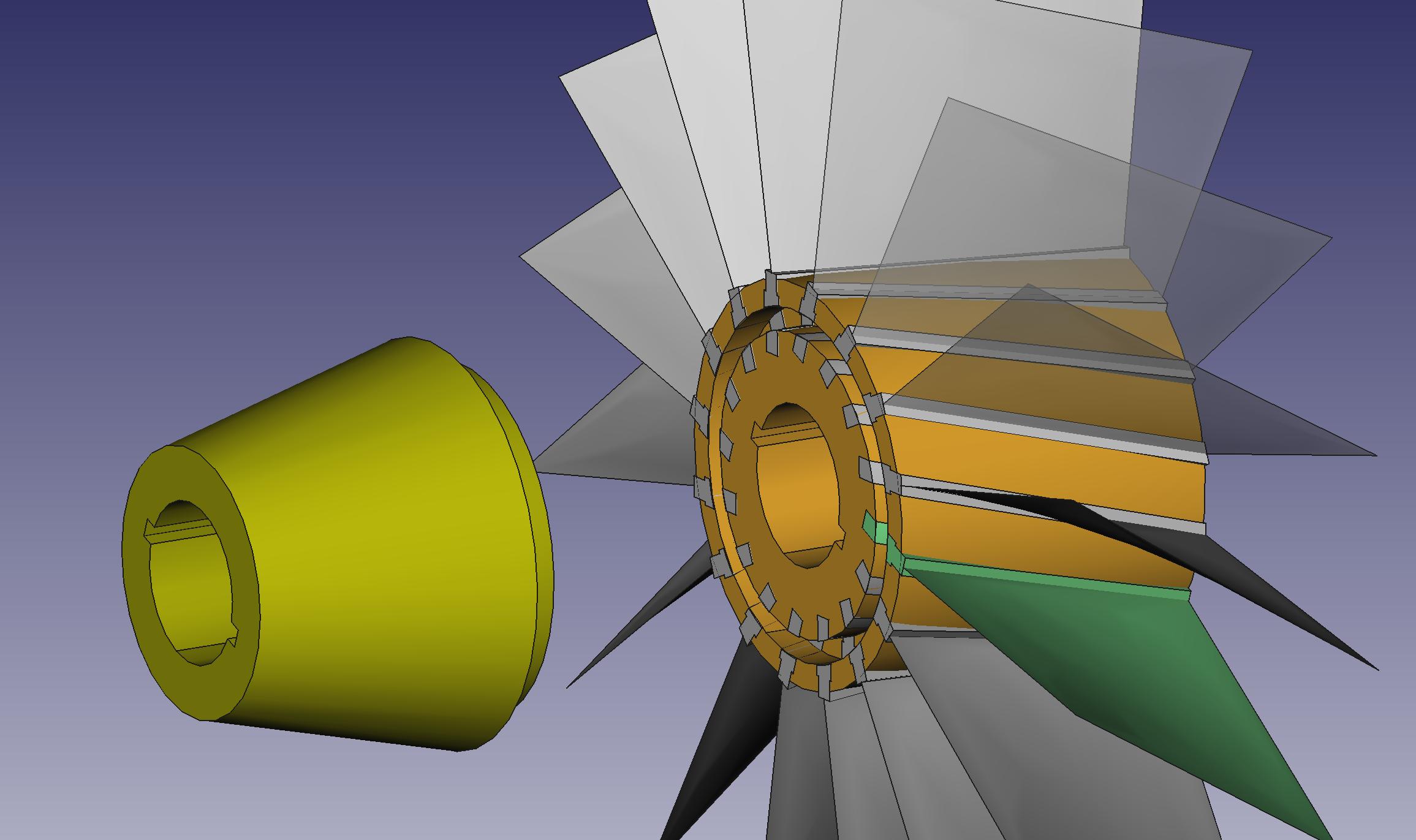
| 01:58, 22 February 2011 | Interblade1.jpg (file) |  |
166 KB | Exploded view of a simple compressor blade fixation design. Between each level, a conic piece like the yellow on this picture is placed and plugs onto a new gray piece like the one in the background, which supports the blades. | 1 |
| 04:01, 29 December 2010 | Pintle engine paper.pdf (file) | 1.33 MB | TRW pintle engine heritage and performance characteristics Gordon A. Dressler, J. Martin Bauer. 2000. TRW copyright. | 1 | |
| 03:58, 29 December 2010 | Rocket book.tar.gz (file) | 278 KB | BOOK: HOW to DESIGN, BUILD and TEST SMALL LIQUID-FUEL ROCKET ENGINES Backup archive from http://www.risacher.org/rocket/ | 1 | |
| 17:45, 24 December 2010 | Restone tank.jpg (file) |  |
99 KB | Center unit of the redstone launcher, basically made of the propellant tank. From http://www.myarmyredstonedays.com/Photos/page8/shell_03.html . | 1 |
| 08:43, 17 November 2010 | S RD107 Head.jpg (file) |  |
78 KB | Cut of the injector plate of the RD-107 engine | 1 |
| 14:17, 23 October 2010 | Datasheet DS1374.pdf (file) | 268 KB | The datasheet of the DS1374 I2C 32-bit binary counter watchdog RTC with trickle charger and reset input/output. | 1 | |
| 19:07, 29 January 2010 | Turbofan craftedshaft.svg (file) | Error creating thumbnail: /bin/bash: line 1: convert: command not found
|
108 KB | updating length and turbine number | 2 |
| 19:06, 29 January 2010 | 500px-Turbofan craftedshaft.svg.png (file) |  |
68 KB | 2 | |
| 11:40, 29 January 2010 | 500px-Turbofan operation.svg.png (file) |  |
78 KB | white bg | 2 |
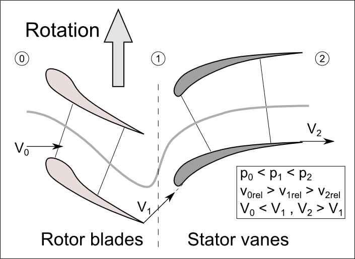
| 11:21, 29 January 2010 | Turbofan operation.svg (file) |  |
88 KB | Turbofan principle | 1 |
| 21:28, 25 January 2010 | Rocket trajectory.png (file) |  |
35 KB | croping picture | 5 |